Hardware
- The hardware consists of
- Microcontroller, Arduino Uno or compatible.
- Display, a 2x16 LCD shield with control buttons, AKA the dfRobot shield.
- Motor, a 4-pin (PWM-controlled) computer fan.
- Suitable power supply for the Arduino board.
- Switching transistor(s), fan connector.
Microcontroller
The Arduino Uno is inexpensive, and the Chinese “compatible” clones work fine. The pin connections are:
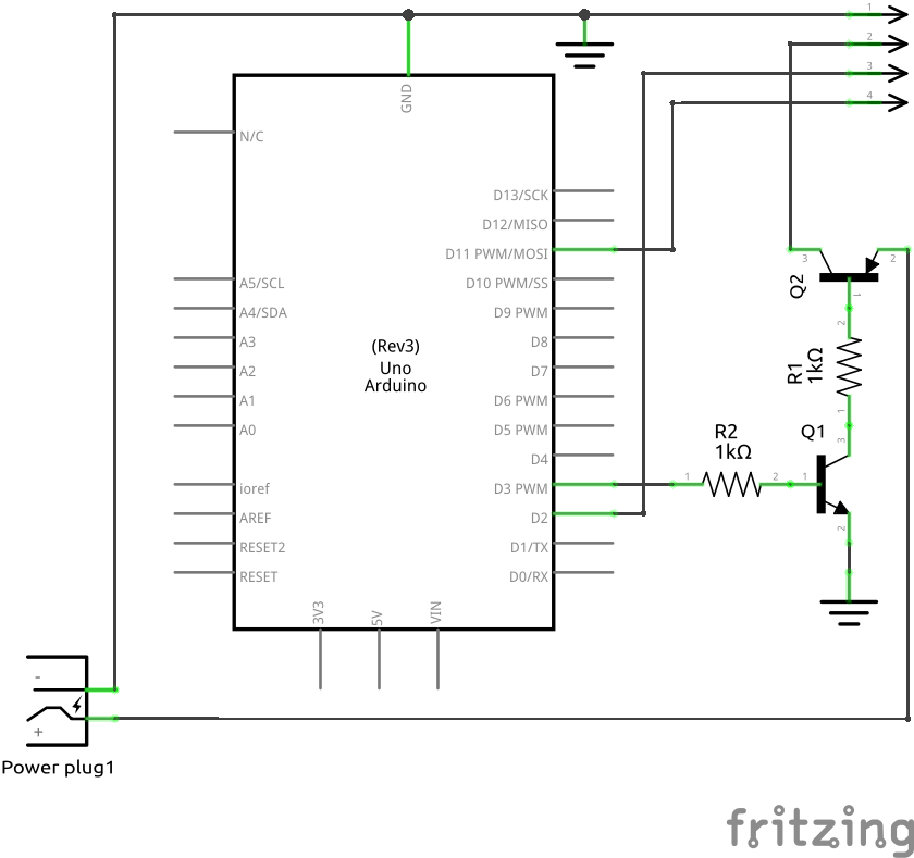
- 2: Fan RPM sense. To pin 3 on fan connector.
- 3: Start. To input of switching transistor(s).
- 11: PWM out. To pin 4 on fan connector.
Additionally, wires are soldered to the negative and positive terminals of the Arduino’s DC barrel jack for ground, and to supply 12 V to the switching transistor(s), respectively.
LCD
The “dfRobot” shield integrates a 2-row, 16-column LCD with control buttons connected via resistor matrix to the Arduino A0 analog input. Only the up, down, and select buttons are used.
Motor
Computer fans are cheap and easily available, and can probably be salvaged from discarded computers. The prototype uses a 60 mm fan from an old AMD heatsink. Ensure the fan is a 4-pin type, which uses a pulse-width-modulated signal to control rotation speed.
Power Supply
Almost any DC plugpack with 2.1 mm barrel jack will work. Voltage should be 9 or 12 volts, which will affect the RPM range of the fan used. If the RPM range is too high using a 12 V adaptor, change it over to a 9 V one.
Switching Transistor(s)
The 12 V to the fan needs to be switched using the 5 V output from the Arduino. For the prototype, an NPN+PNP pair of BJTs were used, as they were in my parts box. A single n-channel FET would work and reduce the part count. Ensure the transistor(s) selected can handle the current draw from the fan, approximately 1 A. The schematic for the BJT pair is as follows: